
High Capacity Salt Cells: Engineering Specifications, Scaling Criteria, and Dynamic Performance from 50g/h to 500g/h Output
When managing water treatment project expansions, scaling the electrolytic chlorine production capacity from a modest 50 g/h to a heavy-duty 500 g/h is far more complex than simply multiplying the active plate surface area of a standard residential or light-commercial unit. As the output escalates, the system encounters severe compounding technical challenges, including exponential current attenuation, localized thermal runaway, rapid hydrogen gas accumulation, and high hydraulic head loss. High-capacity electrochemical modules require radical re-engineering across their structural dimensioning, electrocatalytic mass loading, and rectifier integration. This technical review deconstructs the critical design parameters and performance benchmarks required when transitioning from light-commercial cells to true industrial electrochlorinator cell matrixes, providing an empirical selection guide for engineers executing electrochlorination system scaling.
Dimensional Architecture and Hydraulic Flow Dynamics Under Volumetric Scaling
Low-yield 50 g/h configurations operate within highly forgiving fluid dynamics frameworks. Utilizing compact inline housings and standard 2-inch pipe plumbing, these cells require only nominal flow rates to complete electrolyte circulation and flush out minor gaseous byproducts. However, attempting to scale output simply by lengthening the titanium substrate tracks creates an engineering failure vector. Elongating the plates causes fluid velocity to drop significantly near the rear exit zones, creating hazardous hydrodynamic stagnation areas. These dead zones trap localized heat and exponentially accelerate calcite scale precipitation.
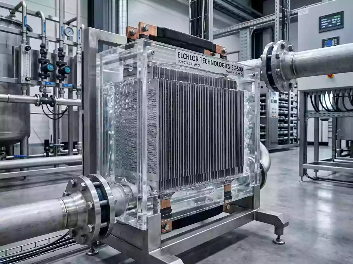
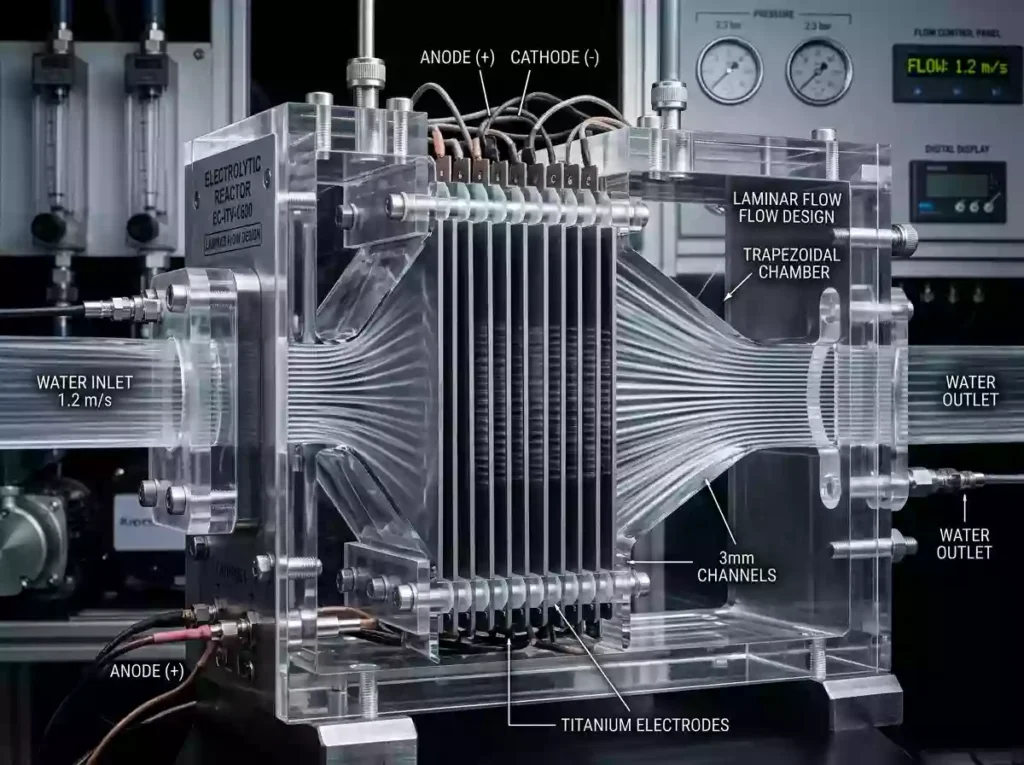
To engineer a reliable 500 g/h industrial electrochlorinator cell, the entire chamber geometry must be structurally reconfigured. The interior transitions to a multi-plate parallel matrix array, accommodated by external connections to diverse industrial pipelines via compact, low-dead-volume flange interfaces. The housing is hydrostatically optimized into a streamlined, inverted-trapezoid profile. This specialized shape perfectly balances the fluid velocity profile across the entire grid—maintaining a balanced velocity of 0.8–1.5 m/s between plates—which minimizes total pipeline pressure drops, completely eliminates thermal dead zones, and ensures unobstructed fluid kinetics throughout the reactor.
Amperage Demands, Rectifier Topologies, and Busbar Metallurgy
A 50 g/h high capacity salt cell typically operates under a mild electrical load of 20 to 30 Amperes, which is easily managed by standard single-phase switch-mode power supplies. This basic electrical topology is highly cost-effective for localized, low-demand applications. Conversely, a heavy-duty 500 g/h chlorinator running under standard salinity parameters demands a continuous current load exceeding 200 to 300 Amperes. To sustain this intensive electrochemical reduction without voltage fluctuation, the power infrastructure must upgrade to industrial-grade, three-phase high-frequency rectifiers.
Operating under such massive amperage places extreme stress on electrical connections, making conventional titanium terminal lugs completely non-viable. Titanium’s low electrical conductivity triggers severe current crowding effects at the contact points, generating destructive heat that can melt terminal seals. To resolve this, Century designs custom silver-plated pure copper busbars and heavy-duty reinforced terminal studs. Engineered for elite conductivity, these specialized distribution plates evenly distribute the current load while minimizing I2R resistive power loss. This metallurgical security prevents localized overheating, ensures uniform current delivery to each individual anode leaf, and maintains a stable cell voltage across the entire stack for long-term continuous operation.
Electrocatalytic MMO Coating Formulations and Mass Loading Differentials
Light-yield 50 g/h modules generally run on intermittent cycles where the wear from concurrent oxygen evolution reactions is structurally negligible, allowing standard Ruthenium-Iridium MMO coatings to achieve their target lifecycles. However, a 500 g/h high capacity salt cell operates under continuous, full-load industrial stress. This unrelenting current density intensifies substrate oxidation, placing the catalytic lattice under extreme electrochemical fatigue that can trigger rapid passivation in low-tier coatings.
For these intense commercial applications, Century re-engineers the catalytic formulation by integrating Iridium-Tantalum stabilized interlayers beneath the active topcoat to form an exceptionally stable, corrosion-resistant ceramic matrix. This optimized mmo electrode coating actively suppresses the parasitic Oxygen Evolution Reaction (OER) and prevents the dissolution of active components. Even when subjected to harsh, low-salinity water chemistry or erratic water temperatures, the matrix firmly anchors the catalytic layer to prevent delamination. This safeguards a highly consistent and stable salt cell chlorine output, significantly extending the effective operational lifespan of the core infrastructure.
Safety Architecture: Managing Massive Hydrogen Gas Evolution and Thermal Dissipation
Scaling chlorine production by a factor of ten yields a matching, geometrically amplified increase in hazardous byproduct discharge. A 500 g/h chlorinator operating at full operational capacity continuously generates massive volumes of hydrogen gas
2H2O+2e−→H2↑+2OH−
If this gas is not instantly swept from the chamber, it creates a severe “gas-lock” phenomena. These trapped gas pockets blind the active electrode surfaces, disrupt electrical continuity, halt electrolysis, and introduce catastrophic risks of localized flammable gas ignition. To mitigate these risks, high-capacity commercial modules integrate a comprehensive safety envelope. The upper ceiling of the cell chamber is cast with a distinct upward-sloping, anti-gas-lock profile that naturally channels rising micro-bubbles toward the primary discharge manifold. This structural gas management is coupled with industrial gas-forced dissipation assemblies. The released hydrogen is instantly diluted and scattered below explosive concentration limits via specialized ventilation loops, completely preventing gas accumulation and ensuring absolute facility safety under heavy hydrogen gas evolution water treatment processes.
Application Parameters: Matching Output Capacities to Project Logistics
Accurately balancing production output with real-world demand is the core axiom of water treatment system design; the precise capacity of the commercial salt chlorinator cell must match the actual disinfection dynamics of the site. Light-commercial models delivering 50 g/h to 100 g/h are precision-calibrated for basins under 1,000 m³, luxury hospitality pools, and small architectural water features, easily leveraging scheduled overnight off-peak hours to complete free available chlorine replenishment.
Conversely, heavy-duty systems delivering 500 g/h or higher are custom-built for municipal waterworks, large-scale commercial water parks, and industrial cooling towers. In these high-turnover environments, an abundant and unyielding salt cell chlorine output is mandatory to enforce uninterrupted biocidal and microbial control. Engineering system specifications based accurately on total daily water circulation volume and organic treatment loads prevents small components from running under destructive electrical overloads, eliminates capital resource waste, and ensures long-term, high-efficiency, and highly economical facility operation.